The Electronics part 2
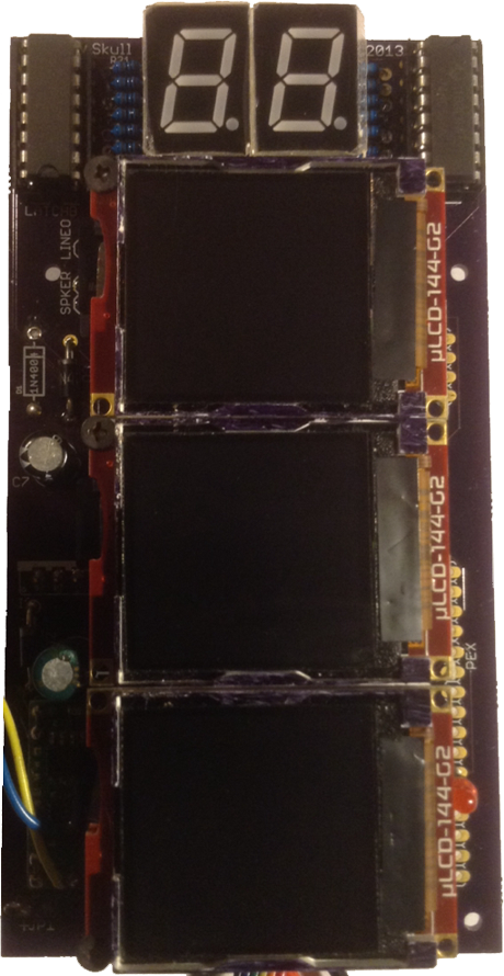
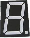
LED Display:
The LED display could easily have been
simulated on the top display, but I thought that
would detract from the originality of the game. I
have always been a fan of 7 segment numeric
displays so leaving it off was not an option.
Sound:
While the sounds produced by the original
Tower are basically old school microcontroller
Pulse Width Modulated audio, they are quite
distinctive and add to the retro experience. In
testing I was able to reproduce the musical
scores but the other sound effects would take a
long time staring at an oscilloscope and tapping
on a keyboard trying to program what I would
see, this would also require a working tower that I
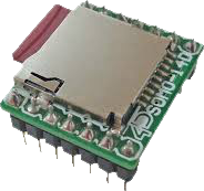
didn't have. Luckily the sound samples are
available for downloading on the internet. I would
need a sound module. I selected the SOMO-14D
sound module and converted the samples to AD4
format, added an 8ohm .25 watt speaker and was
very happy with the result.
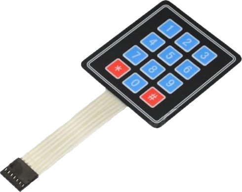
Keypad:
I used the same style 3x4 matrix 12 key
membrane keypad that I used to fix the keypad in
the original tower.
Microcontroller:
I added up how many inputs and outputs I
would need and estimated that I would need
roughly 16K of flash ram for the programming. I
chose the Pic 18F452. It can run at 40mhz, has
32K of flash, more than enough I/O, and I got it for
less than $5.
The Circuit Board:
I have made quite a few circuit boards at home
but I decided this would be a great project to have
my first professional board made. The final lay out
and size of the board would of course depend on
the tower I would build. So after bread boarding
all of my test circuits, I sat down and fired up
Eagle Cad to build the schematic.